Switch Board Wiring Connection Diagram
Switchboard schematic and wiring diagrams. A set of as built prints and instructions manuals covering the switchboards are.

Wiring Diagram of the Distribution Board Mechanical
It consists of symbols to represent the components and lines to represent.

Switch board wiring connection diagram. How to wire rcd & distribution board? This page takes you on a tour […] The frame of the switchboard houses and supports the other components.
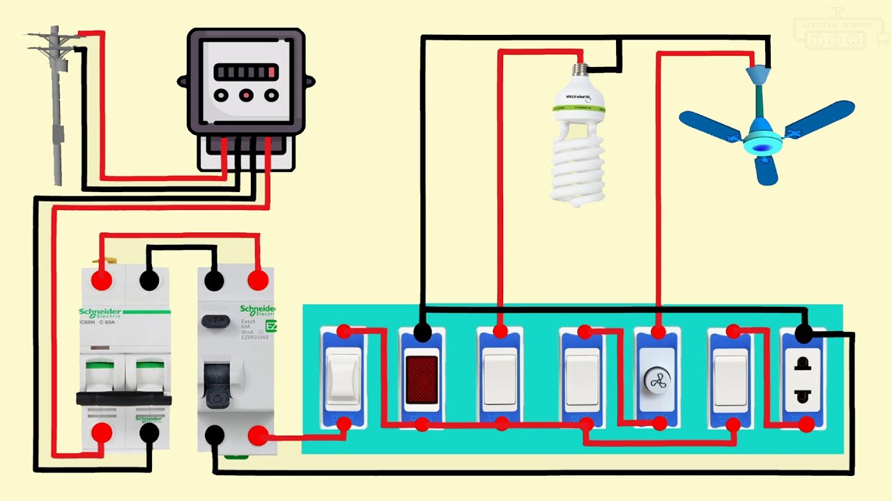
In the below wiring diagram the phase line is connected parallel to the light switch and the plug socket switch. April 14, 2021 · wiring diagram. Main switchboard wiring diagram.the neutral link is a very important part of the safety aspects of an electrical installation.
How to wire up a switchboard in the below wiring diagram, the phase line is connected parallel to the light switch and the plug socket switch. A switchboard is the heart of a building's electrical system. After wiring is completed, all connections should be carefully checked against the diagrams to insure that all connections are correct and proper.
Domestic switchboard wiring diagram australia estate wiring diagram land house cartoon png download 1230 1239 set free release transparent electric 18. All the electricity used in your building passes through the switchboard. With this sort of an illustrative manual, you will have the ability to troubleshoot, stop, and complete your tasks with.
Diy home electric supply with rcd wiring installation tutorial. A wiring diagram is a simple visual representation of the physical connections and physical layout of an electrical system or circuit. 63 a fuse (1 pcs) 2.
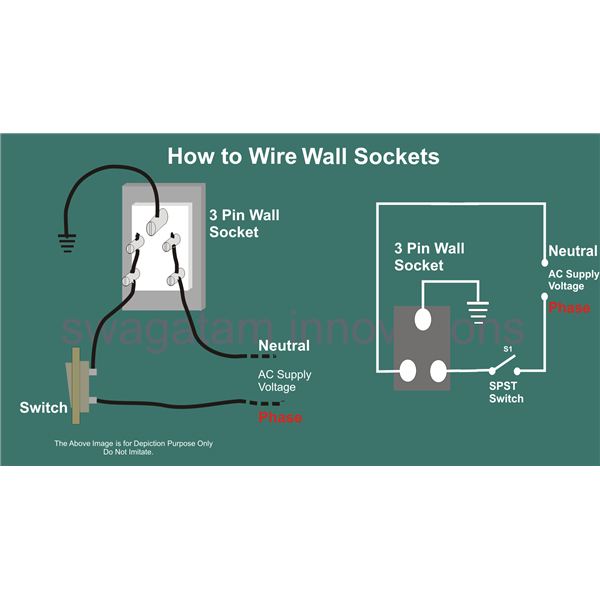
About press copyright contact us creators advertise developers terms privacy policy & safety how youtube works test new features press copyright contact us creators. Electrical switch board wiring diagram electrical switch board connect in 2021 electrical switches house wiring electricity 3 phase electrical switchboard wiring diagram and designing electrical control board general technica electrical switches house wiring home electrical wiring kamar didngin bertema kartun chil97 tips trik electrical circuit diagram. Here, one pole of the both spst (single pole single throw) switches s1 & s2 are connected to the phase line of the supply.
The given circuit is a basic switchboard wiring for a light switch and 3 pin socket with control switch. Here, one pole of the both spst (single pole single throw) switches s1 & s2 are connected to the phase line of the supply. This page takes you on a tour of the.
Single pole (sp) switch (4 pcs) 4. 230v indicator (1 pcs) 3. Siemens switchboards have a depth measurement ranging from 20 to 58 inches.
Electrical wiring installation of the distribution board with rcd (single home phase supply from utility pole & energy meter to the consumer unit. The switchboard is the central hub for all your power, so it is vital that it is maintained and kept in safe working order. 230v electronic fan regulator (1 pcs) 6.
2 pin 3 pin socket connection in switchboard house wiring switch b in 2021 house wiring sockets connection how to make an electric extension board two sockets with individual switch and indicator or fuse youtube extension board electrical projects electricity switch board connections in telugu how to make electrical switch board youtube electrical. A set of "as built" prints and instructions manuals covering the switchboards are How to wire up a switchboard.
How to wire up a switchboard in the below wiring diagram, the phase line is connected parallel to the light switch and the plug socket switch. Suzuki outboard ignition switch wiring diagram. An optional height of 70 inches with widths of 32, 38, or 46 inches is also available.
Rcd, cb and mcb circuit breaker wiring connection and. Failure to follow these instructions will result in death or serious injury. The standard siemens switchboard frame is 90 inches high and 32 or 38 inches wide.
It is also a good idea to watch some videos prior to installation to avoid unnecessary problems. Distribution board installation with rcd (residual current device). A switch in an electronic device is used to interrupt the flow of electricity or electriccurrent.electrical switches are binary devices they can be either co.
A wiring diagram is a simple visual representation of the physical connections and physical layout of an electrical system or circuit. Let us suppose that realization of a main distribution switchboard is required, to be placed immediately on the load side of a 2000kva mv/lv transformer.three 850a outgoing feeders from this switchboard supply other distribution. The earth wire may be connected to consumer's neutral
32a double pole (dp) switch (1pcs) 5.
house wiring switch board connection diagram electrical

House Electrical Switchboard Wiring Diagram Wiring Diagram
Switchboard Connection Diagram

Australian Switchboard Wiring Diagram Digital Lost

Electrical Switch Board Wiring Diagram Electrical Switch
![]()
Circuit Diagram Of Electric Board Wiring Diagram Line

Board Connection Wiring Diagram ALYSE277

Image result for Switch Board Wiring Connection
Wiring A Switch Board Brilliant Wiring Diagram Electrical

Inverter Connection To Switchboard Home Wiring Diagram


Zhiheng Luo's Wiring World Panel Work Switchboard

2 pin & 3 pin socket connection in switchboard House
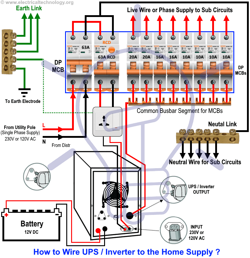
Inverter Main Connection Home Wiring Diagram

Switch board connection wiring diagram two switch 1socket
house wiring electrical switch board connection diagram

very simple switch board wiring connection YouTube

how to wire an rcd on board Google Search Electrical

Domestic Electrical Switchboard Wiring Diagram schematic

Pin on woodworking